Q&A
A Safety Machine is mainly verified to EN ISO 13849-1: PL e (Cat. 4) requirement in accordance with:
EN 60947-5-3, EN ISO 14119, EN 62061: SIL CL 3…etc.
Safety gate with sensors can provide the all-around protection and keep operators from any injury caused by the running machine during operation. Safety system includes not only basic mechanical safety protections, but also electrical double safety circuit control.
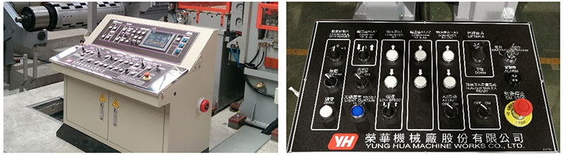
For Total Safety Oriented Operation, Three Operation Modes are available on control panel with key lock.
- Manual Mode feed/adjustment (Operator must operate with two hands + machine limited speed)
- Auto Run Mode (Operators stay in safe distance + machine can run max. speed)
- Maintenance Mode (Most electrical and hydraulic power are disabled and locked except specified maintenance function.)
CE safety machine requires to meet the main directives:
2014/30/UE Electromagnetic Compatibility
2006/42/EC Machinery Directive
2006/95/EC Low Voltage Directive
For different machines, different standards are requested, such as:
EN ISO 12100 :2010 Safety of machinery - General principles for design – Risk assessment and risk reduction
EN ISO 13849-1:2015 Safety of machinery - Safety-related parts of control systems -Part l: General principles for design
Our machines design meets required EN ISO standards, applicable for CE Safety Certification.
-
Safety Covers for moving parts is the basic when machine is running.
-
Mechanical Safety Pins together with Electrical Safety Sensors to lock the moving parts and deactivate the driver power when adjustment or maintenance is processing.

-
Emergency Stop not only on main operation panels, but also other accesses.
- Safety lock for maintenance engineer to secure their work in safe circumstances.
- Tension roll is surface coated with Polyurethane which is softer than metal, but it is endurable to take friction and sharp burr on slit strip edge to guide slit strips running in steady way.
- Tension rolls is designed to produce tension by about 2% speed slower on tension rolls than recoiling speed. This approximately 2% speed differential can generate electricity feed-back to decrease the machine power consumption. The money saved years round can cover the expense for replacement of PU when the roll surface is critical damaged.

The main differences are listed in below table.
|
Item description |
Tension Rolls |
Belt Bridle |
|
1. Scratch on material |
No |
No |
|
2. Cost investment |
Low |
High |
|
3. Life time |
Long |
Short |
|
4. Maintenance expense |
Low |
High |
|
5. Time to adjust after replacement |
Quick |
Slow |
|
6. Operational electricity consumption |
2% feed back |
High |
|
7. Additional cooling device |
No need |
Yes |
Leveler roll diameter design is a complex calculation including material tensile strength, palsticication ratio, roll clearance, roll deformation,
For example, metal material of tensile strength 400 Mpa, the reference diameter of leveler rolls are below.
Ø50mm for material max. 2.0mmt.
Ø60mm for material max. 3.0mmt,
Ø70mm for material max. 4.5mmt,
If one leveler can't cover all the material thickness , two levelers or exchangeable double cassette levelers can be considered.
For example, one cassette leveler with Ø50mm rolls can manage material up to 2.0mm in thickness. but maximum material is 3mm in thickness, then another cassette with Ø60mm leveler rolls will fit. The product range of same cut-to-length line extended from 2mm thickness to 3mm thickness.
Some customers even choose levelers of Ø50mm rolls and Ø70mm rolls in separate two, so the product range is enlarged from maximum 2 mm to 4.5 mm.
Laser Guides for Height and Edge are our auxiliary devices to help operator to load on coil easily by laser mark guidance. The devices are controlled by buttons on operation panel. This function is particularly useful for CE and EN ISO-13849-1 safety machines, of which the operator stay outside the fence in distance to load on coil.
Laser Height Guide can help operator follow the laser mark to align the coil height to top of mandrel.
Laser Edge Guide can help operator follow the laser mark to align coil at center of mandrel.
Two types, stop-to-cut type with guillotine shear or non-stop cutting type with rotary or flying shear. The differences are as below table.
|
ItemType |
Stop-to-cut |
Non-stop cutting |
|
Shear type |
Guillotine shear |
Rotary or flying shear |
|
Shear drive |
Hydraulic |
Servo motor |
|
Cutting process |
Feeding – stop – waiting shear to cut (one cycle) |
Non-stop feeding & shear tracking length to cut |
|
Material thickness |
0.2~ 25mmT |
0.2~ 4.5mmT |
|
Scratch on surface |
No scratch |
No scratch |
|
Roll mark on surface |
Depends on material |
No mark |
|
Critical required surface |
Not recommended |
Recommended |
|
Productivity |
As standard base |
About 2~5 times higher |
In short, the advantage of rotary shear and flying shear is faster production speed, no roller mark on material surface, and that of guillotine shear is cost lower.
EPC is the initial of “Edge Position Control” which is important for the quality products of both cut-to-length machine and slitting machine.
The EPC starts functional from Uncoiler positioning to follow the side guide before leveler.
EPC dynamically keep the material coil edge aligned constantly so to make sure diagonal accuracy of cut sheets or edge straightness of slit strips.
If without EPC, especially when the thin material coil band is off edge line, coil band might get damaged on the edge whilst coping with side guides which try to force the band edge back to the line,
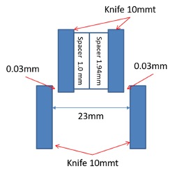
In normal case of slitting knife clearance is 10% of the material thickness, e.g. if the material is 0.3mm in thickness, the knife clearance is 0.3mmx10%=0.03mm.
In order to get proper clearance, you need to have special spacer 1.94mm.
Below are some examples for your combination reference.
-
To get slit width 23mm: (needs special spacer 1.94mm)
10(knife)*2+0.03(clearance)*2+1.94(spacer)+1.0(spacer)=23mm -
To get slitting width 23.1mm:
10(knife)*2+0.03(clearance)*2+1.94+1.1 (spacer)=23.1mm -
To get slitting width 24mm:
10(knife)*2+0.03(clearance)*2+1.94+2 (spacer)=24mm